Cable List

On the Cabling tab, either clicking Cable List or selecting Cable List > Cables list pane shows or hides the Cable List pane. In this pane, you can utilize many (but not all) of the functions of the Cable Manager tool.
Opening the Cable List pane consumes a 'Cable Router' license, and closing the pane or leaving the Cabling tab releases the license again.
Changes made to cables in the Cable List pane can be reverted or re-applied using the standard Undo and Redo commands found in the Plant Modeller quick access toolbar.
Cable List pane
In the Cable List pane, you can do the following:
-
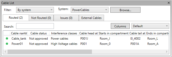
You can use the Routed, Not Routed, and Issues tabs to browse and manage 3D cables created in Plant/Outfitting according to their routing status.
Selecting any one of these tabs shows the total number of cables in each category after the tab's title.
These three tabs share the same Filter and Search functions, column layout, and context menu.
-
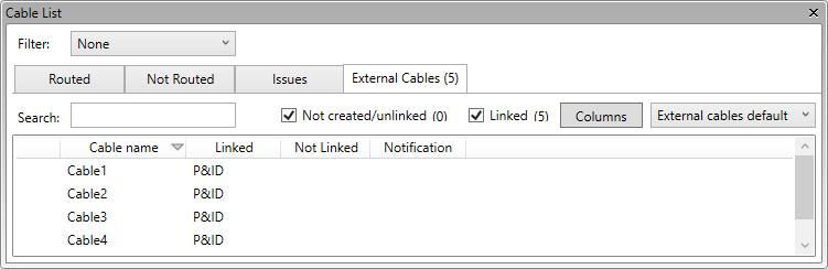
You can use the External Cables tab to browse and manage cables defined in CADMATIC P&ID, CADMATIC Electrical, or third-party software.
Selecting this tab shows the total number of external cables after the tab's title.
This tab has its own Filter and Search functions, column layout, and context menu.
On any tab, you can use the main filters, the search function, and the additional filters to find the required cables.
You can change the column layout with drag-and-drop or by clicking Columns, and sort information by clicking column headers.
Selecting one or several cables enables the applicable commands in the context menu, such as routing a cable or deleting the existing route.
Selecting cables displays their properties in the Properties pane. The (editable) attributes and the approval status of checked-out cables can be modified through the property pane.
Cable list filters | Commands for 3D cables | Commands for external cables
Cable list filters
You can filter the cable lists by selecting a suitable main filter.
Filter:
-
None – Select this option to list all cables.
-
By system – Select this option to only list the cables that use a specific system. You can select the system from the drop-down list or the object browser.
-
By query – Select this option to only list the cables that match a COS query. You can select the query from the drop-down list or through Manage Queries.
-
Cables in selected part – Select this option to only list the cables that are routed through the selected object. The object can be a cable node, cable segment, or host object of the cable routing network (cable tray, cable penetration, or conduit). You can see the object's current fill rate on this tab, and you can click Show Fill Rate View to display a fill rate view, if supported by the object.
After selecting the main filter, you can filter the cable lists further as described below.
-
Search – You can filter the cable lists by entering a search string. The search string can correspond to any portion of a visible column's value.
Filters for cables with issues:
-
Changed route – Select this option to display cables whose route has changed.
-
Broken route – Select this option to display cables whose route is broken.
-
Head/tail change – Select this option to display cables whose head or tail location has changed.
Filters for external cables:
-
Not created/unlinked – Select this option to display external cables that have not been created in Plant Modeller yet or have been created but are not yet linked to a 3D cable.
-
Linked – Select this option to display external cables that are linked to a 3D cable.
Manage Queries
In the Cable List pane, the Manage Queries button opens the Select and Manage Stored Queries for Cables dialog.
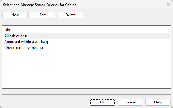
In this dialog, you can manage your COS queries that are used for filtering the cable list. These queries are private—they are not visible to other users.
-
To create a query, click New. Define the selection rules for the query and save it with a descriptive name along with the .cqsr extension.
-
To edit a query, select it and click Edit.
-
To delete a query, select it and click Delete.
Selecting a query and clicking OK applies that query to the cable list.
Commands for 3D cables
The context menu of the Routed, Not Routed, and Issues tabs contains the following commands.
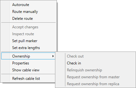
Note: Commands that modify cables require the cables to be either checked out or at least available for check-out. They will check out (or request ownership of) cables that are available but not checked out. If cable's status is 'Approved', the user is prompted whether to allow the approvals to be revoked and then approve them again after the operation.
|
Action |
Description |
|---|---|
|
This command routes the selected cables using the shortest/cheapest route. |
|
|
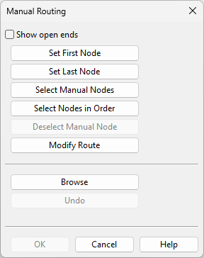
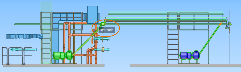
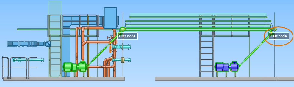
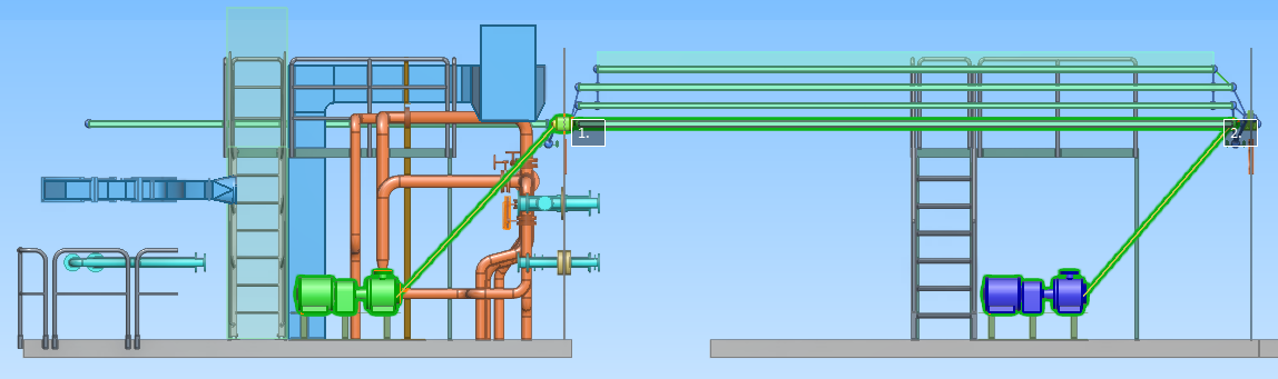
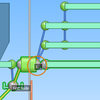
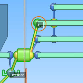
This command opens the Manual Routing dialog where you can pick routing nodes manually. It also displays the texts "Head" and "Tail" in their respective locations within the work views. The cable node to use as the start or end node must have a node ID. You can add node IDs via Modify or Node Ids in the Cable Router tool. Using manual routing, you can make selections that auto-routing does not make:
The Manual Routing dialog contains these commands:
|
|
|
This command deletes the route of the selected cables. |
|
|
This command accepts the route and the head/tail changes of the selected cables. |
|
|
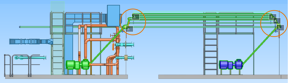
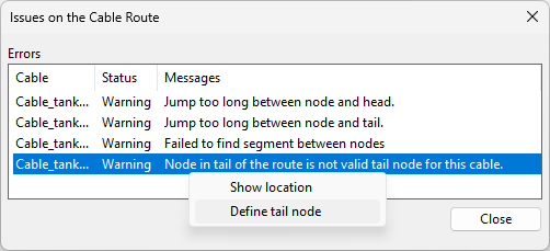
This command tries to illustrate why the route of the selected cables is broken by inspecting the current route and showing all the issues in it. You can select an issue from the list, and open the context menu to see what can be done with it. Most issues enable you to at least see their location in the 3D model. The following issues can also be fixed if the cable is checked out:
|
|
|
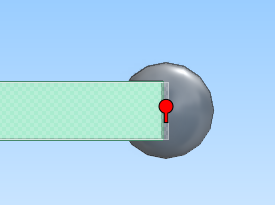
This command can be used to select the cable node where you want to set the pull marker or remove the existing pull marker. Press Enter to confirm the action. |
|
|
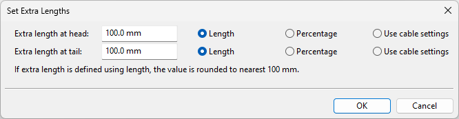
This command opens the Set Extra Lengths dialog where you can define extra length for the head and tail sections of the selected cables.
|
|
|
Through this menu you can perform the following commands.
|
|
|
This command opens the Properties pane, if not open already. |
|
|
This command opens the Cable View dialog, displaying the routes of the selected cables. You can adjust the view through Cable View Settings. |
|
|
This command reloads all the details of the cables, if for some reason the information has not been updated automatically. |
Commands for external cables
The context menu of the External Cables tab contains the following commands.
|
Action |
Description |
|---|---|
|
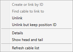
This command links the selected integration objects to 3D cables based on the cable ID. If previously linked objects have been unlinked with Unlink but keep position ID, this command is able to automatically re-link them. If an integration object has duplicates, this command selects the newest one, based on creation time in COS. |
|
|
This command opens the Find and Select Objects dialog for linking the selected integration object to a 3D cable. You can use the search functions described in Find to find the required cable. |
|
|
This command unlinks the selected integration objects, including their duplicates, from the 3D cables. This unlink action renames the affected 3D cables using the format Unlinked_<COS_oid>. Note: This command removes the 'Original Position Info' attribute from the 3D cable, preventing automatic re-linking. You will still be able to re-link the integration objects manually, using Find cable to link to. To unlink individual integration objects, use Details > Unlink from Model Object instead. |
|
|
Unlinks all integration objects, including their duplicates, from the 3D cables. This unlink action renames the affected 3D cables using the format Unlinked_<COS_oid>. Note: This command keeps the 'Original Position Info' attribute in the 3D cable, enabling Create or link by ID to re-link the integration objects. |
|
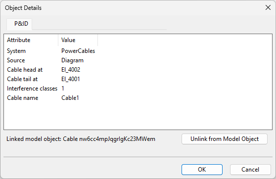
|
Opens the Object Details dialog. This dialog displays a tab for each integration object with the given position ID. On each tab, you can see the attributes of the integration object and the possible link to a 3D cable. If there are multiple tabs of the same type, it means that the integration object has duplicates in COS. If the integration object is linked to the wrong (or non-existing) 3D cable, or the integration object is a duplicate of the intended integration object, you should unlink the object, then correct the linking, and possibly request the project administrator to delete any unwanted duplicates from COS.
|
|
|
This command opens the Cable View dialog, displaying the head and tail objects of the selected cable, if they are found in the model. You can adjust the view through Cable View Settings. |
|
|
This command reloads all the details of the external cables, if for some reason the information has not been updated automatically. |